
Launch Controler For Solid Rocket Motors
CONTENTS
- Introduction
- Launch Controller Operation
- Power
- Battery Charging
- Controller Circuit
- Controller Components
- Controller Construction
- Testing the Controller
INTRODUCTION
The designed brief was to provide a simple launch control unit.
The Launch Controller is designed to be used to directly launch model, mid and high power solid motor rockets.
When designing my home made launch controller I set out to build a robust launch controller with enough battery capacity so that I wouldn’t have to worry about them going flat at the launch siteL
This is my first go at designing a launch controller, I have tried to keep it simple and as easy to construct as possible.
LAUNCH CONTROLLER OPERATION
The controller does not have built in continuity detection, a number of people have said that there is a possibility of misfires due to the continuity circuit setting off the igniters. So I decided against having this feature.
The launch lead is plugged into the back launch controller.
The key is then inserted into the launch controller and rotated 90 degrees clockwise to the arm position. If the battery is working normally, a Green panel light will light up.
The switch is fitted with a flip top toggle switch cover. Lift the cover and flip the switch, a second red panel light will light up. (When the toggle switch cover is closed, it automatically forces the switch into the OFF or safe position.)
Perform a 5 second count down
Push the large red button to launch you rocket.
POWER
The launch controller is fitted with a 12v 7 Amp hours Sealed Lead Acid rechargeable battery. (See components)
BATTERY CHARGING
I use a 12V Sealed Lead-Acid Battery Charger, this requires me to remove the battery from the Launch controller when charging, i don’t have a problem with this. But if you want you can always change the design to incororate charging without removing the battery.
ELECTRONIC CIRCUT
The launch controller electronic circuit is designed to keep the launch control / firing circuit as simple as possible – for ease of maintenance and reliability.
CONTROLLER COMPONENTS
Most of the part for the launch controller was sourced from Maplin Electronics. Below is a list of the parts used.
MAPLIN PART NUMBER
|
DESCRIPTION
|
QUANTITY REQUIRED
|
A20GB
|
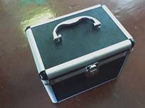
120 Abs/Aluminium Cd/DVD Storage Box
|
One
|
LL30H
|
12V Sealed Lead-Acid
|
One
|
MG47B
|
7ah 12v Rechargeable Lead-Acid Gel
|
One
|
N42AT
|
Missile Style Toggle Switch Cover
|
One
|
|
3 Pin XLR Socket
|
Two
|
|
3 Pin XLR Plug
|
Two
|
XR60Q
|
Heavy Duty Loudspeaker Cable
|
Two
|
JK25C
|
10A SPST Toggle Switch
|
One
|
RK82D
|
Large Red Push Button Momentary Switch
|
One
|
N07BB
|
8mm 12v Panel
|
Two
|
XR32K
|
Wire 3202 Black
|
Two
|
XR34M
|
Wire 3202 Brown
|
Two
|
JH88V
|
Lucar Female Blue
|
One Pack
|
I also ordered the following locking keyswitch from RS Components |
||
319-809 |
Double Pole Lock Switch made by Lorlin
Manufacturers Part No.SRL5MD2
|
One |
CONTROLLER CONSTRUCTION
1, Connect the loudspeaker cable to two of the pins in one of the 3 pin XLR Connector.
2, connect the other 3 pin XLR Connector to the other end of the loudspeaker cable, make sure your pin connections are identical to the XLR Connector in step one.
3, Open the cd/dvd storage box and remove the disk sleeves
4, Solder two wires to the connectors on the 3 pin XLR Socket( ensure you use the same two conectors you used on the plugs in step one and two above
5, Cut out a hole in the back of the storage box for the 3 pin XLR Socket and fix in place with M3 machine screws, washers and nuts.
6, Cut some 1mm thick aluminium sheet so it fits inside the top of the storage box, and rests on the lip of the C channel that the cd storage sleeves sat on.
7, Whilst the aluminium sheet is in place in the storage box drill a 2.5mm hole in each corner of the aluminium sheet ensure that the holes go through the bottom of the C channel that the aluminium sheet is resting on.
8 Remove the aluminium sheet and make the holes you has previously drilled bigger by running a 3.5mm drill through them.
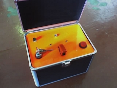
9, Mark on the aluminium sheet where you are going to mount you switches and lights, and cut out the holes.
10, Fix all switches and lights into there holes.
11, Connect up the switches and lights as per the circuit diagram and check the circuit for operation.
12, Construction completed
TESTING THE CONTROLLER
1, Ensure your battery is fully charged, connect to the circuit and fit into the bottom of the case.
2, Fit the aluminium sheet complete with switches installed into the storage box, use 4 M3 self tapping screws to secure the aluminium sheet in place.
3, Connect one end of the 3 Pin XLR lead to the launch controller, and the other end to the launch cable reel.
4, Connect the crocodile clips from the other end of the launch control cable to a 12v car bulb.
5, insert the key into the controller and turn, you should have a power light.
6, Flip the switch to arm the firing circuit, you should have a second light.
7, Press the red Launch button, and the bulb connected to the crocodile clips should light.
8, Test Complete